Migen and LiteX
“Hello world!” - Blink an LED
FIXME: Add the Migen and LiteX equivalent for the Verilog above.
Wishbone Bus
Migen is an HDL embedded in Python, and LiteX provides us with a Wishbone abstraction layer. There really is no reason we need to include a CPU with our design, but we can still reuse the USB Wishbone bridge in order to write HDL code.
We can use DummyUsb to respond to USB requests and bridge USB to
Wishbone, and rely on LiteX to generate registers and wire them to
hardware signals. We can still use wishbone-tool to read and write
memory, and with a wishbone bridge we can actually have code running on
our local system that can read and write memory on Fomu.
Go to the litex directory and build the design;
$ python3 workshop.py --board $FOMU_REV
lxbuildenv: v2019.8.19.1 (run .\workshop.py --lx-help for help)
lxbuildenv: Skipping git configuration because "skip-git" was found in LX_CONFIGURATION
lxbuildenv: To fetch from git, run .\workshop.py --placer heap --lx-check-git
Warning: Wire top.basesoc_adr has an unprocessed 'init' attribute.
Warning: Wire top.basesoc_bus_wishbone_ack has an unprocessed 'init' attribute.
Warning: Wire top.basesoc_bus_wishbone_dat_r has an unprocessed 'init' attribute.
...
Info: Device utilisation:
Info:            ICESTORM_LC:  1483/ 5280    28%
Info:           ICESTORM_RAM:     1/   30     3%
Info:                  SB_IO:     4/   96     4%
Info:                  SB_GB:     8/    8   100%
Info:           ICESTORM_PLL:     1/    1   100%
Info:            SB_WARMBOOT:     0/    1     0%
Info:           ICESTORM_DSP:     0/    8     0%
Info:         ICESTORM_HFOSC:     0/    1     0%
Info:         ICESTORM_LFOSC:     0/    1     0%
Info:                 SB_I2C:     0/    2     0%
Info:                 SB_SPI:     0/    2     0%
Info:                 IO_I3C:     0/    2     0%
Info:            SB_LEDDA_IP:     0/    1     0%
Info:            SB_RGBA_DRV:     0/    1     0%
Info:         ICESTORM_SPRAM:     4/    4   100%
...
Info: [ 55530,  59533) |********+
Info: [ 59533,  63536) |************************************************+
Info: [ 63536,  67539) |******************************+
Info: [ 67539,  71542) |*************+
Info: [ 71542,  75545) |********************+
Info: [ 75545,  79548) |************************************************************
5 warnings, 0 errors
Load it onto Fomu:
$ dfu-util -D build/gateware/top.dfu
dfu-util 0.8
Copyright 2005-2009 Weston Schmidt, Harald Welte and OpenMoko Inc.
Copyright 2010-2014 Tormod Volden and Stefan Schmidt
This program is Free Software and has ABSOLUTELY NO WARRANTY
Please report bugs to dfu-util@lists.gnumonks.org

Opening DFU capable USB device...
ID 1209:5bf0
Run-time device DFU version 0101
Claiming USB DFU Interface...
Setting Alternate Setting #0 ...
Determining device status: state = dfuIDLE, status = 0
dfuIDLE, continuing
DFU mode device DFU version 0101
Device returned transfer size 1024
Copying data from PC to DFU device
Download        [=========================] 100%       104090 bytes
Download done.
state(7) = dfuMANIFEST, status(0) = No error condition is present
state(8) = dfuMANIFEST-WAIT-RESET, status(0) = No error condition is present
Done!
$
If you get an error message about missing modules, check you have all submodules cloned and setup with;
$ git submodule update --recursive --init
$
Take a look at build/csr.csv. This describes the various regions
present in our design. You can see
memory_region,sram,0x10000000,131072, which indicates the RAM is 128
kilobytes long and is located at 0x10000000, just as when we had a
CPU. You can also see the timer, which is a feature that comes as part
of LiteX. Let’s try reading and writing RAM:
wishbone-tool 0x10000000
wishbone-tool 0x10000000 0x98765432
wishbone-tool 0x10000000
Aside from that, there’s not much we can do with this design. But there’s a lot of infrastructure there. So let’s add something.
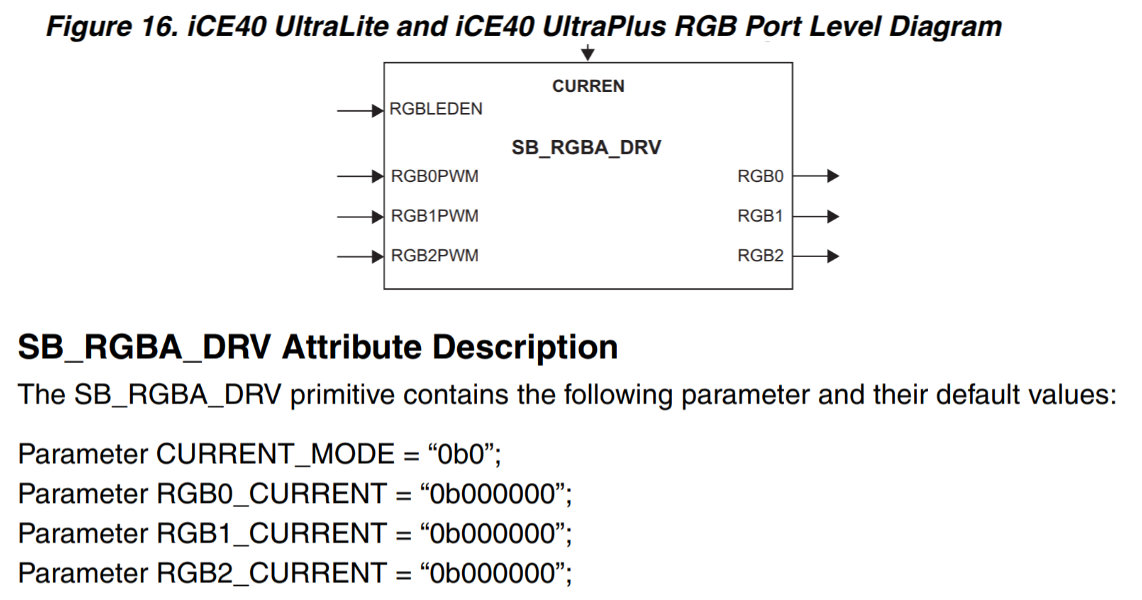
This is the RGB block from the datasheet. It has five inputs:
CURREN, RGBLEDEN, RGB0PWM, RGB1PWM, and RGB2PWM. It
has three outputs: RGB0, RGB1, and RGB2. It also has four
parameters: CURRENT_MODE, RGB0_CURRENT, RGB1_CURRENT, and
RGB2_CURRENT.
This block is defined in Verilog, but we can very easily import it as a Module into Migen:
class FomuRGB(Module, AutoCSR):
    def __init__(self, pads):
        self.output = CSRStorage(3)
        self.specials += Instance("SB_RGBA_DRV",
            i_CURREN = 0b1,
            i_RGBLEDEN = 0b1,
            i_RGB0PWM = self.output.storage[0],
            i_RGB1PWM = self.output.storage[1],
            i_RGB2PWM = self.output.storage[2],
            o_RGB0 = pads.r,
            o_RGB1 = pads.g,
            o_RGB2 = pads.b,
            p_CURRENT_MODE = "0b1",
            p_RGB0_CURRENT = "0b000011",
            p_RGB1_CURRENT = "0b000011",
            p_RGB2_CURRENT = "0b000011",
        )
This will instantiate this Verilog block and connect it up. It also
creates a CSRStorage object that is three bits wide, and assigns it
to output. By having this derive from AutoCSR, the CSRStorage
will have CSR bus accessor methods added to it automatically. Finally,
it wires the pads up to the outputs of the block.
We can instantiate this block by simply creating a new object and adding
it to self.specials in our design:
...
    # Add the LED driver block
    led_pads = soc.platform.request("rgb_led")
    soc.submodules.fomu_rgb = FomuRGB(led_pads)
Finally, we need to add it to the csr_map:
...
    soc.add_csr("fomu_rgb")
Now, when we rebuild this design and check build/csr.csv we can see
our new register:
csr_register,rgb_output,0xe0006800,1,rw
We can use wishbone-tool to write values to 0xe0006800 and see
them take effect immediately.
You can see that it takes very little code to take a Signal from HDL and expose it on the Wishbone bus.